
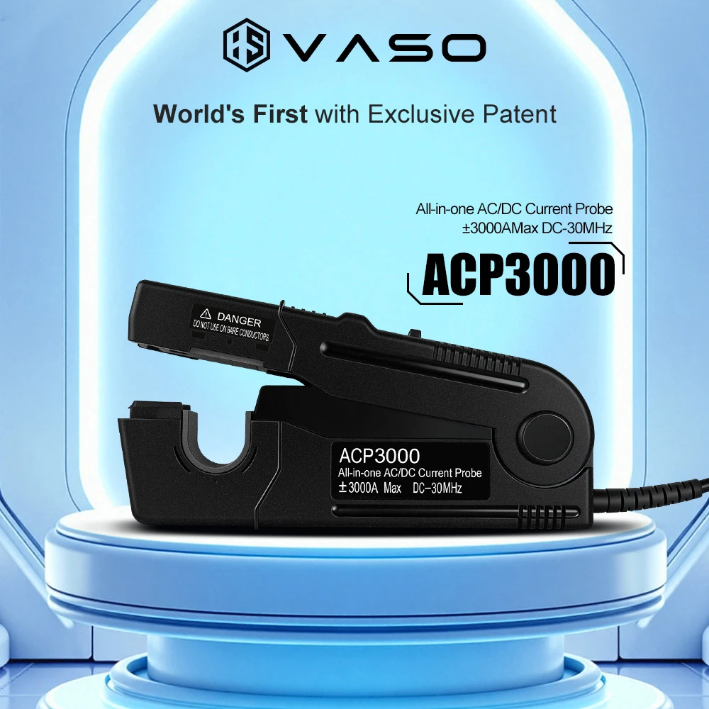
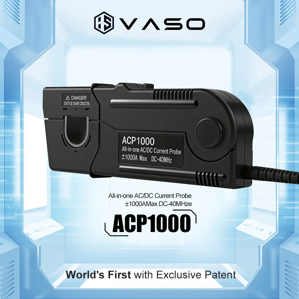
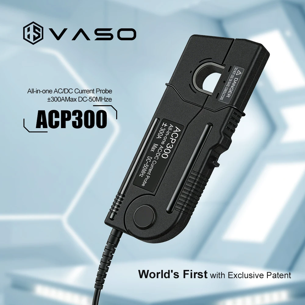
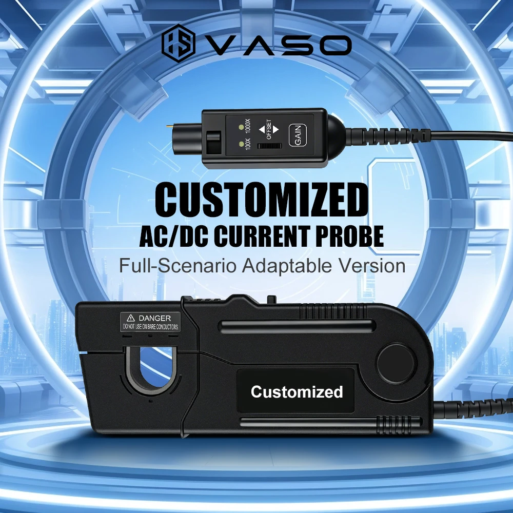
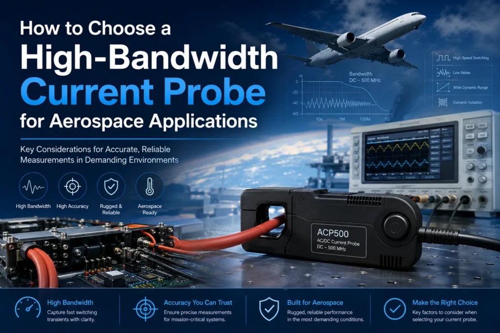
Quick answer: Selecting a high-bandwidth current probe for aerospace work means matching four things to your test: frequency range (typically DC or a few Hz up to 100 MHz–1 GHz), current handling (from milliamps to hundreds of amps), insertion impedance low enough to avoid loading the circuit under test, and compliance with aerospace EMC standards such as MIL-STD-461 and RTCA DO-160. Rogowski coils and Hall-effect/current-transformer hybrid probes are the two dominant technologies, chosen based on whether you need DC response or only need to characterize fast transients.
Aerospace power and avionics systems pack switching power supplies, motor drives, and digital buses into a shielded, weight-constrained airframe where electromagnetic interference (EMI) can compromise flight-critical systems. Measuring current accurately — without disturbing the circuit or missing a fast transient — is central to EMC qualification, power integrity debug, and lightning/HIRF (High-Intensity Radiated Field) testing. This guide walks through the engineering criteria that matter, the standards that govern the work, and a practical selection process.
Why Bandwidth Matters More in Aerospace Than in Most Other Fields
Aerospace current measurements have to capture two very different phenomena:
- Steady-state and low-frequency currents from power distribution, DC-DC converters, and motor drives (DC to a few MHz).
- Fast transients from switching edges, lightning-induced surges, and RF coupling that can extend into the tens or hundreds of MHz — sometimes into the GHz range for modern wide-bandgap (SiC/GaN) power electronics.
A probe with insufficient bandwidth will simply not “see” the fast edge of a transient, which can hide a real EMI compliance failure until the aircraft is in flight test — an expensive place to discover it. This is why aerospace test programs typically specify probes with bandwidth well above the highest frequency of interest, following the common engineering rule of provisioning at least 3–5x the highest harmonic you need to resolve.
Core Selection Criteria
1. Frequency Bandwidth and Rise-Time Response
Define the bandwidth from the actual signal you’re measuring, not a generic number. For switching converter ripple, DC–5 MHz may suffice; for characterizing SiC/GaN switching edges or lightning-induced transient response per DO-160 Section 22, you’ll want probes rated to 30–100 MHz or higher. Check the probe’s rise-time specification as well as its -3 dB bandwidth point, since a flat frequency response through the band avoids amplitude and phase distortion of the measured waveform.
2. Current Range and Sensitivity
Aerospace test articles range from microamp-level sensor lines to hundreds of amps on primary power buses. A probe’s dynamic range (its ratio of maximum to minimum resolvable current) determines whether one probe can cover both a quiescent current draw and an inrush transient without saturating or losing resolution.
3. Insertion Impedance
Any current probe inserted in a circuit adds impedance. In high-frequency aerospace circuits, even a few ohms of insertion impedance can shift circuit behavior enough to invalidate a measurement. Clamp-on Rogowski coils and split-core current transformers are popular precisely because they add negligible insertion impedance compared to inline shunt resistors.
4. DC Response Requirement
Rogowski coils cannot measure true DC current — they respond only to changing current (di/dt), then integrate the signal, which introduces a low-frequency roll-off. If a measurement includes steady-state DC (e.g., battery bus current), a Hall-effect-based or hybrid current transformer probe is required instead. Pure AC current transformers face the same DC limitation.
5. Isolation Voltage and Safety Rating
Aerospace power buses can carry voltages from 28 VDC to 270 VDC (or higher on more-electric-aircraft architectures), plus transient overvoltage during faults. The probe’s isolation voltage rating, and its rated CAT (measurement category), needs margin above the bus voltage plus expected transients.
6. Environmental Ruggedness
Bench-grade probes rarely survive flight-line or environmental-chamber conditions. For qualification testing, look for probes rated for the temperature, vibration, and humidity profiles in DO-160 Sections 4–8, or MIL-STD-810 for ground support equipment.
7. Connector and Form Factor
Clamp-on jaw size must physically fit the harness or bus bar being measured, and cable routing in an aircraft rack often constrains probe body size and cable length between the probe head and amplifier.
Aerospace-Specific Standards to Know
| Standard | What It Covers | Why It Matters for Probe Selection |
|---|---|---|
| MIL-STD-461 | EMI/EMC emission and susceptibility limits for military platforms | Defines the frequency ranges (CE101/CE102, RE101/RE102) your current probe must cover during conducted emissions testing |
| RTCA DO-160 | Environmental and EMC qualification for airborne equipment | Section 19 (induced signal susceptibility) and Section 22 (lightning) often require probes with bandwidth into the tens of MHz |
| SAE ARP standards | Aerospace recommended practices for wiring and power quality | Referenced for power quality current measurements on 28V and 115V aircraft buses |
Test engineers should confirm which specific paragraph of MIL-STD-461 or DO-160 governs their test plan before locking in a probe, since the required frequency range and current handling differ significantly between sections.
Rogowski Coil vs. Hall-Effect vs. Current Transformer: Which to Use
- Rogowski coil: Best for high-bandwidth AC and transient measurement, flexible clamp form factor, no core saturation, but no DC response. Common choice for switching-edge and EMI transient work.
- Hall-effect (or hybrid Hall + CT) probe: Measures DC through high frequency, making it the standard choice when a bus carries both steady current and fast transients. Typically has lower bandwidth ceiling than a pure Rogowski coil.
- Current transformer (CT): Simple, robust, and often the least expensive option for AC-only measurements within a moderate bandwidth, but shares the no-DC limitation of Rogowski coils and can saturate under high transient current.
A Practical Selection Process
- Define the measurement band. List the lowest and highest frequency components you must capture, including any transient or surge content.
- Determine DC vs. AC-only requirement. This alone often eliminates half the available probe technologies.
- Estimate current range, including worst-case inrush or fault current, and check against the probe’s stated saturation current.
- Check insertion impedance against your circuit’s sensitivity to loading.
- Confirm isolation and safety rating against bus voltage plus expected transient overvoltage.
- Cross-reference the governing standard (MIL-STD-461, DO-160, or program-specific test plan) for any mandated bandwidth or accuracy requirement.
- Verify environmental rating if the probe will be used outside a lab bench.
- Confirm oscilloscope or data-acquisition compatibility, including the probe’s output type (voltage output vs. requiring a dedicated amplifier) and connector.
Perguntas frequentes
What bandwidth do I need for aerospace EMI testing? It depends on the specific MIL-STD-461 or DO-160 test section, but many conducted-emissions and transient-susceptibility tests call for probes with bandwidth from a few kHz up to 100 MHz. Always confirm the exact frequency range in your test plan rather than assuming a generic figure.
Can one probe measure both DC bus current and high-frequency switching transients? Yes, but only with a Hall-effect or hybrid Hall/CT probe design, since Rogowski coils and standard current transformers cannot resolve steady DC current.
Why does insertion impedance matter for aerospace circuits? Aerospace power and signal circuits often operate at low source impedance and high frequency, where even small added impedance from the probe can distort the measured current or shift circuit resonance, producing a misleading result.
Is a clamp-on probe accurate enough for EMC certification testing? Clamp-on Rogowski and CT probes are widely used and accepted in EMC certification testing, provided they meet the bandwidth, accuracy, and calibration requirements specified in the governing standard and are used within their rated current and frequency range.
Conclusion
Choosing a high-bandwidth current probe for aerospace work is a matter of matching the probe’s frequency response, current range, insertion impedance, DC capability, and environmental rating to the specific requirements of your test — and to the governing standard, whether that’s MIL-STD-461, DO-160, or a program-specific test plan. Getting this selection right the first time avoids costly re-testing and reduces the risk of missing a real EMI or power-integrity issue before it reaches flight test.