
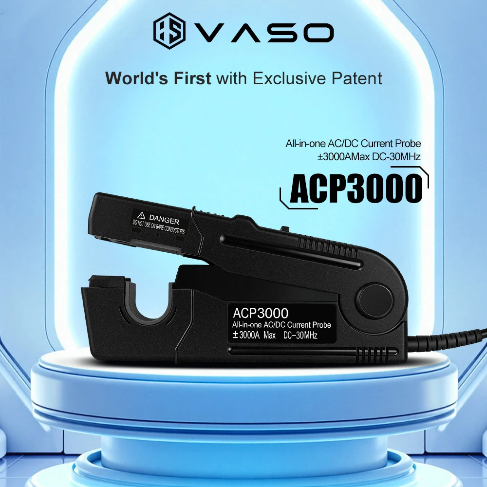
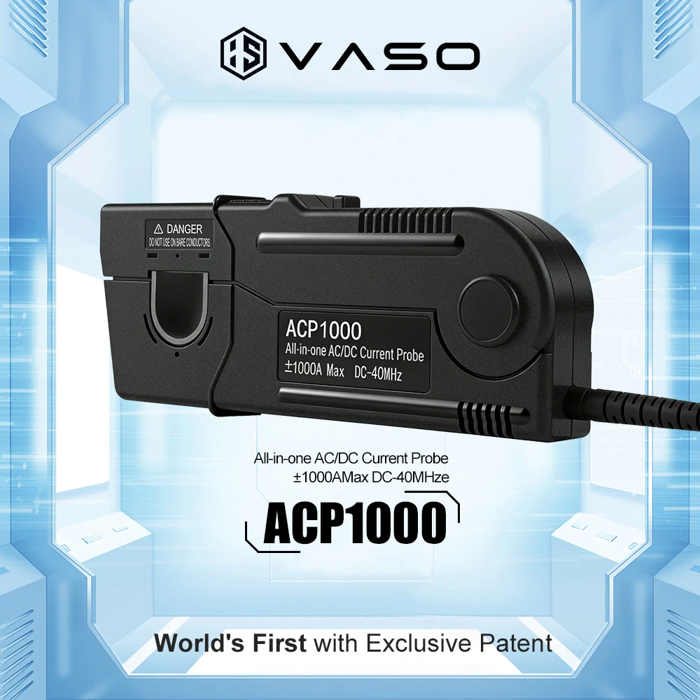
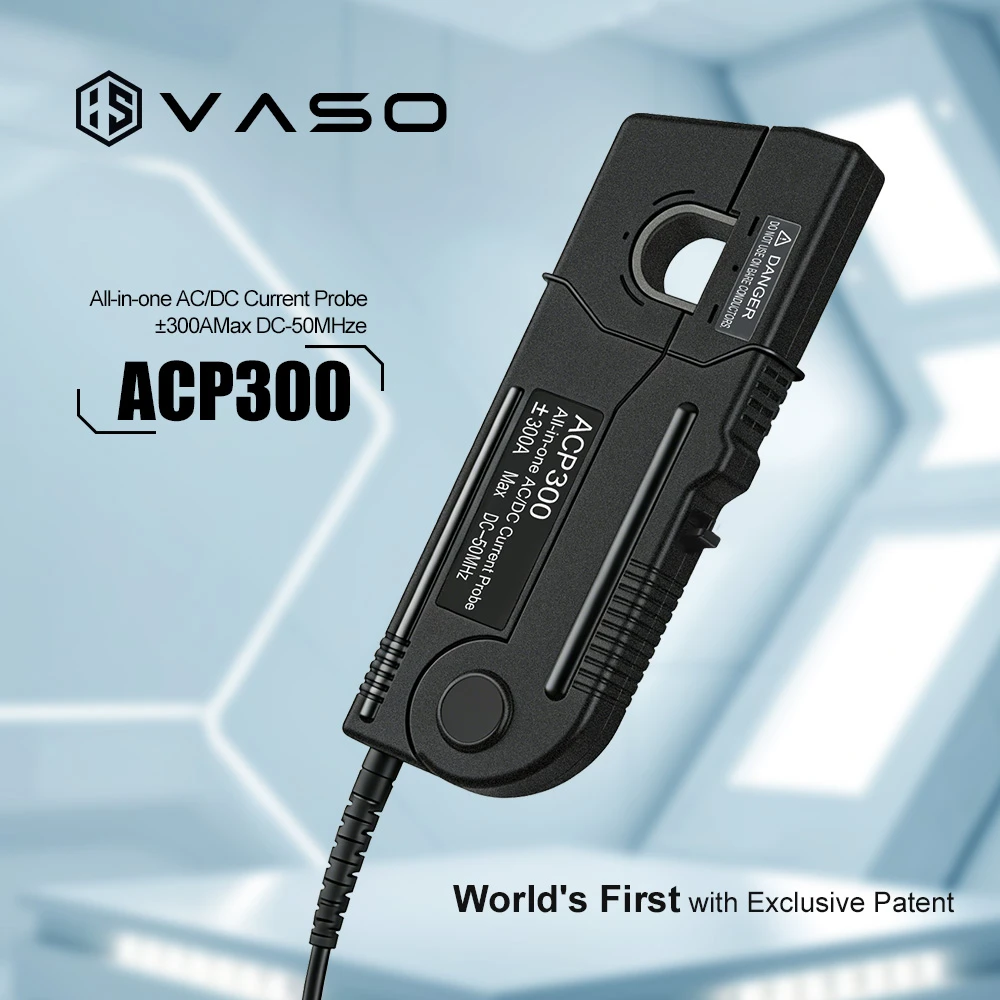
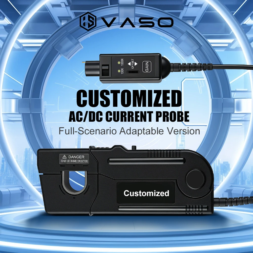
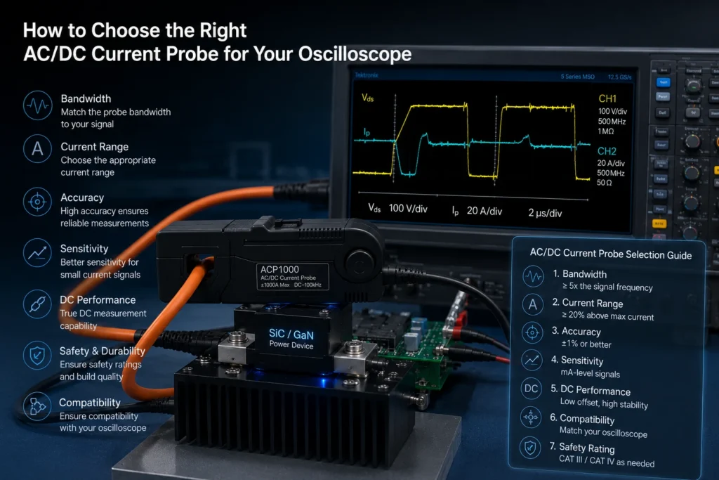
An AC/DC current probe is a measurement accessory that clips around a conductor and converts the current flowing through it into a proportional voltage signal that an oscilloscope can display. Unlike voltage probes, current probes do not require the circuit under test to be broken or opened, which makes them essential for power electronics, motor drive, and energy conversion measurements where non-intrusive sensing is required.
Selecting the correct probe is not a matter of picking the highest-specification model available. It requires matching the probe’s technology, range, bandwidth, and safety rating to the specific characteristics of the signal being measured and the environment in which the measurement takes place.
What an AC/DC Current Probe Measures
A true AC/DC current probe is capable of capturing both the alternating and direct current components of a signal simultaneously. This distinguishes it from AC-only probes, which use a simple current transformer and cannot detect DC offset or DC-only currents, and from DC-only probes, which lack the bandwidth to follow fast switching transients. Applications such as switch-mode power supply design, motor control, battery charging circuits, and inverter testing typically involve waveforms with both components, making a combined AC/DC probe the appropriate default choice.

Core Selection Criteria
1. Current Range
The probe must accommodate the full expected range of the signal, including transient spikes, not just the steady-state RMS or average value. A probe rated for a maximum continuous current lower than the peak current in the circuit will saturate, producing a clipped or distorted waveform on the oscilloscope display. Engineers generally select a probe with headroom of at least 20 to 30 percent above the anticipated peak current to avoid saturation during inrush or fault conditions.
2. Bandwidth
Bandwidth determines the highest frequency component the probe can accurately reproduce. Switching power supplies, motor drives using pulse-width modulation, and RF circuits generate harmonic content well above their fundamental switching frequency. As a general guideline, probe bandwidth should be at least five to ten times the fundamental switching or signal frequency to capture rise times and harmonic content without significant attenuation or phase error. Insufficient bandwidth rounds off fast edges and can mask overshoot or ringing that is critical to a design evaluation.
3. Sensing Technology
Three sensing technologies dominate current probe design, each suited to different measurement needs:
- Hall effect probes use a magnetic sensor to detect both AC and DC fields, making them capable of true AC/DC measurement from 0 Hz upward. They are the standard choice when DC content must be captured.
- Current transformer (CT) probes rely on electromagnetic induction and can only detect changing (AC) currents. They offer high bandwidth and low noise but cannot measure DC.
- Rogowski coil probes are flexible, air-core sensors well suited to high-current, high-frequency AC measurements in tight or irregularly shaped spaces, but like CT probes, they cannot measure DC directly and require an integrator circuit to reconstruct the waveform.
For applications requiring true AC/DC capability, a Hall effect probe, or a hybrid design combining a Hall sensor with a current transformer, is the appropriate selection.
4. Accuracy and Sensitivity
Probe accuracy is typically specified as a percentage of reading plus a fixed offset error, and it directly affects the reliability of power, efficiency, and current-ripple measurements. Sensitivity, expressed in millivolts per amp or amps per division, should be matched to the oscilloscope’s vertical resolution: a probe with output too low relative to the signal of interest will bury small current variations in oscilloscope noise, while excessive gain can push large signals off-screen.
5. Isolation and Voltage Rating
Current probes are inherently isolated from the circuit’s voltage potential because they clamp around a conductor rather than making electrical contact, but each probe carries its own working voltage and CAT (measurement category) rating. Selecting a probe rated below the system voltage or CAT level of the circuit under test creates a serious safety hazard. Probes used on mains-connected or high-voltage power electronics should carry a CAT III or CAT IV rating appropriate to the installation category.
6. Physical Fit and Jaw Size
The probe’s jaw or aperture diameter must physically accommodate the conductor, cable, or busbar being measured, including any insulation. Larger jaw sizes generally reduce bandwidth and sensitivity compared to smaller-aperture probes of the same product family, so the jaw size should be chosen as small as practical for the application rather than defaulting to the largest available option.
7. Connector and Power Compatibility
Current probes typically require external power, either from the oscilloscope itself through a dedicated probe power interface (such as TekProbe, AutoProbe, or similar standards) or from a separate probe power supply and amplifier unit. Compatibility between the probe’s connector, power requirements, and the specific oscilloscope model must be confirmed before purchase, since mismatched interfaces can prevent operation entirely or require an additional amplifier module.
Matching the Probe to the Application
| Application | Key Requirement | Recommended Technology |
|---|---|---|
| Switch-mode power supply design | Wide bandwidth, AC/DC capability | Hall effect or hybrid Hall/CT |
| Motor drive and inverter testing | High current range, harmonic content | Hall effect or Rogowski coil |
| Battery and DC power measurement | True DC accuracy, low drift | Hall effect |
| High-frequency RF or EMI work | High bandwidth, low insertion impedance | Current transformer |
| Field measurements on busbars or large cables | Flexible form factor | Rogowski coil |
Common Selection Errors
Underestimating peak current is one of the most frequent mistakes, since steady-state ratings alone do not account for inrush or fault transients. A second common error is selecting a probe based on nominal bandwidth without verifying that the oscilloscope’s own bandwidth and sample rate are sufficient to display the resulting signal without additional attenuation. A third is overlooking the interaction between probe sensitivity and oscilloscope vertical resolution, which can result in a technically compatible probe that nonetheless produces a poor-quality trace for low-amplitude ripple or noise analysis.
Summary
Choosing the right AC/DC current probe requires matching current range, bandwidth, sensing technology, accuracy, isolation rating, and physical fit to the specific circuit and measurement objective, rather than selecting the highest-rated probe available. For applications combining AC and DC components, such as power converters and motor drives, a Hall effect or hybrid Hall/current-transformer probe with adequate bandwidth headroom and a safety rating matched to the system voltage represents the standard, reliable choice.