



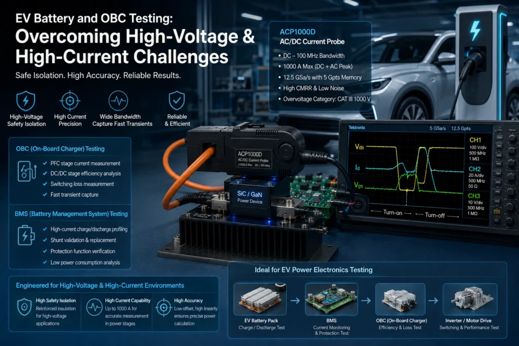
Anyone who has spent time on a bench validating an On-Board Charger or a Battery Management System knows that the specification sheet only tells half the story. A charger rated for 800 V DC and 11 kW sounds straightforward on paper, but the moment you connect real test equipment to a live pack, two problems surface immediately: how do you keep operators and instruments safe at those voltage levels, and how do you measure current with enough accuracy to trust the numbers you’re reporting to a certification body. These two issues — insulation coordination and high-current measurement fidelity — sit at the center of nearly every difficult test campaign in EV power electronics validation.
Why Voltage Class Alone Doesn’t Define the Test Problem
The industry has largely settled on two working voltage bands for traction systems: 400 V architectures, which are still common in mass-market platforms, and 800 V architectures, which are becoming the default for fast-charging-capable vehicles. But the nominal bus voltage is not what determines isolation requirements during testing. What matters is the working voltage under fault conditions, the pollution degree of the test environment, and the overvoltage category the equipment must survive.
IEC 60664-1 remains the reference framework here, and it’s worth actually applying its tables rather than assuming a “1000 V rated” probe or dividing box is automatically adequate. Creepage and clearance distances scale with both voltage and pollution degree, and a lab bench covered in coolant residue, dust from a nearby machining area, or ordinary bench dust is not pollution degree 1, whatever the datasheet assumes. Test fixtures that were adequate for 400 V validation frequently fall short when reused unmodified for 800 V programs, because the required creepage distance roughly doubles rather than scaling linearly.
For OBC and BMS test systems specifically, three isolation classes tend to come up in practice:
Basic insulation is sufficient for internal circuit separation where a single fault does not expose a person to hazardous voltage, but it is rarely enough for the barrier between a high-voltage source simulator and the low-voltage measurement and control electronics that an operator will touch.
Reinforced insulation — providing protection equivalent to double insulation in a single barrier — is what most test system designers specify for the boundary between the HV emulation side (battery simulator, DC source, load bank) and the LV control/DAQ side. This is where isolated amplifiers, isolated ADC front ends, and optically or transformer-isolated gate drive feedback earn their cost premium.
Functional insulation, by contrast, exists purely to allow the circuit to work — it carries no safety guarantee — and confusing it with basic insulation during a risk assessment is a mistake that shows up more often than it should in internal test reports.
Hipot (dielectric withstand) testing and insulation resistance testing under IEC 60950/62368 or the automotive-specific ISO 6469-3 and GB/T 18384/18487 series are not just compliance checkboxes; they are diagnostic tools. A pack or OBC that passes IR testing at 500 V but fails at the higher test voltage specified for its actual working voltage is telling you something about margin, not just pass/fail status, and that margin data matters more once the same design goes into a hot, vibrating, salt-exposed vehicle environment for ten years.
The OBC-Specific Test Problem: Isolation Under Switching Stress
Bench-testing a charger’s control loop with a benign resistive load is a very different exercise from validating it against a real battery emulator running PFC and LLC (or totem-pole PFC plus phase-shifted full bridge) topologies at full power. Two things make OBC testing harder than generic power supply testing:
First, the AC-side to DC-side isolation barrier has to survive not just steady-state voltage but the transient stress from switching edges — dv/dt on the order of tens of kV/µs is common in modern SiC-based chargers. Isolation amplifiers and current sensors that are rated for the DC working voltage can still show measurement error or, worse, degrade over time if their common-mode transient immunity (CMTI) isn’t adequate for the actual switching environment. This is a failure mode that doesn’t show up in a static hipot test — it only appears once the unit is running.
Second, grid-side and battery-side ground reference schemes differ across regions and even across OEM platforms (TN, TT, IT-derived automotive HV systems), and a test bench has to accommodate isolation monitoring — insulation resistance monitoring devices per ISO 6469-3 — without introducing ground loops that corrupt current measurement. Engineers who skip this step often chase phantom measurement noise for days before realizing the isolation monitor itself is injecting a small leakage current into the measurement path.
BMS Testing: Where Small Currents and Large Currents Have to Coexist
BMS validation is arguably the more demanding measurement problem, not because the voltages are unusually high, but because the required dynamic range is brutal. A BMS current sensor has to resolve milliamp-level parasitic drain currents during vehicle sleep mode — critical for state-of-charge accuracy over weeks of parking — while also surviving and accurately reporting several hundred amps during a fast-charge or regenerative braking event. That’s five or six orders of magnitude of dynamic range on a single measurement channel, and coulomb counting accuracy over the life of the pack depends on getting the low end right just as much as the high end.
This is where the choice of current sensing technology stops being an implementation detail and becomes a design decision with real consequences:
Shunt-based sensing, using a low-value precision resistor and a four-wire Kelvin connection, gives excellent linearity, low temperature drift when using manganin or similar alloys, and straightforward traceability to a calibration standard — but it introduces power dissipation and requires very careful PCB layout to avoid thermal EMF errors at the microvolt level, which matters when you’re trying to resolve milliamp currents across a shunt sized for hundreds of amps.
Hall-effect and fluxgate sensors (open-loop and closed-loop) provide galvanic isolation inherently and handle high currents without dissipation, but historically have had weaker low-current linearity and are more sensitive to temperature-dependent offset drift — a real problem for coulomb counting accuracy, since offset error integrates over time into a state-of-charge error that doesn’t self-correct.
Many production BMS designs and matching test systems now combine both: a shunt for the low-to-mid current range where precision matters most, and a Hall or fluxgate sensor for the high-current range, with a defined crossover and reconciliation strategy. Test equipment used to validate these systems has to replicate that same dynamic range and switch cleanly between ranges without discontinuities that would be mistaken for BMS algorithm errors.
Traceable calibration matters more here than in most other areas of automotive electronics testing, because BMS accuracy claims eventually feed warranty and safety arguments about remaining useful capacity. A current measurement chain — shunt or transducer, signal conditioning, ADC, and any digital filtering — should be characterized as a system against a calibration standard traceable to a national metrology institute, not assumed accurate because each component’s datasheet lists a tight tolerance in isolation. Component-level tolerances stack, and gain and offset errors from a sensor, an isolation amplifier, and an ADC reference can combine in ways that exceed the system-level accuracy the test report implicitly claims.
Building a Test Bench That Respects Both Constraints Simultaneously
In practice, the safety isolation and measurement precision requirements pull in opposite directions unless the test architecture is planned deliberately. Adding isolation barriers introduces additional noise sources, propagation delay, and potential nonlinearity — all of which work against the precision needed for BMS validation. A few practices tend to separate reliable test setups from ones that generate disputed data:
Route high-current conductors and their Kelvin sense leads with dedicated, symmetric paths, physically separated from gate drive and switching nodes, to avoid induced noise on the measurement path — a problem that gets worse, not better, at 800 V with faster switching edges.
Validate isolation barriers under actual switching conditions, not just static hipot, since CMTI-related measurement corruption is a dynamic phenomenon.
Specify creepage and clearance for test fixtures against the actual pollution degree of the lab environment, and re-verify fixtures when moving a program from a 400 V to an 800 V platform rather than assuming reuse is safe.
Treat the entire current measurement chain, not individual components, as the unit of calibration, with periodic verification against a traceable reference across the full dynamic range the BMS is expected to see in the field.
None of this is exotic engineering. It’s disciplined application of well-established standards — IEC 60664-1, IEC 61010, ISO 6469-3, and the relevant GB/T series for markets that require it — combined with an honest accounting of how switching-frequency electrical stress differs from the static conditions those standards were originally written to address. The teams that get OBC and BMS validation right are usually the ones that treat isolation coordination and measurement accuracy as a single integrated design problem for the test system, rather than two separate checklist items to satisfy independently.