
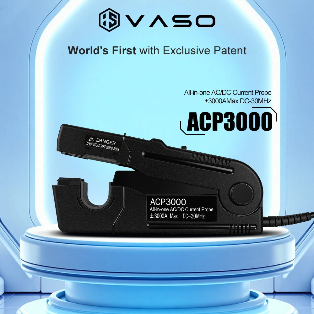
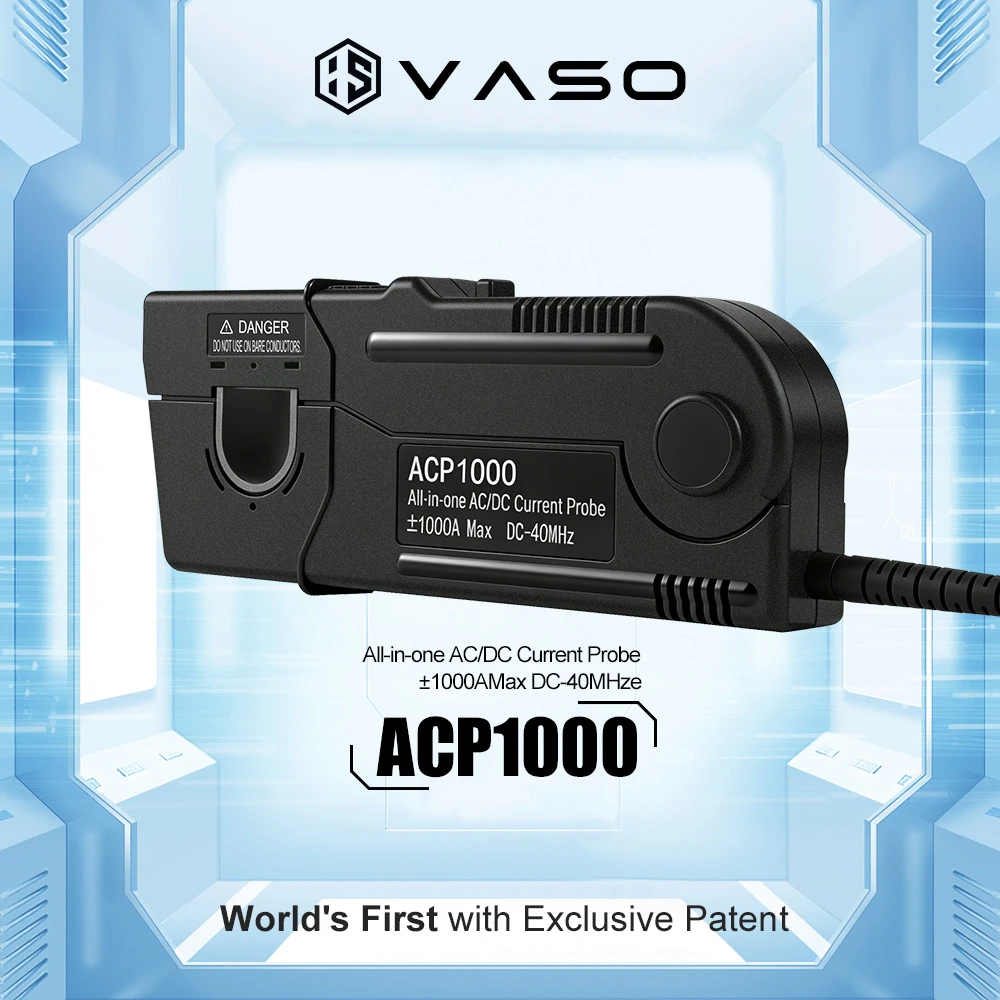
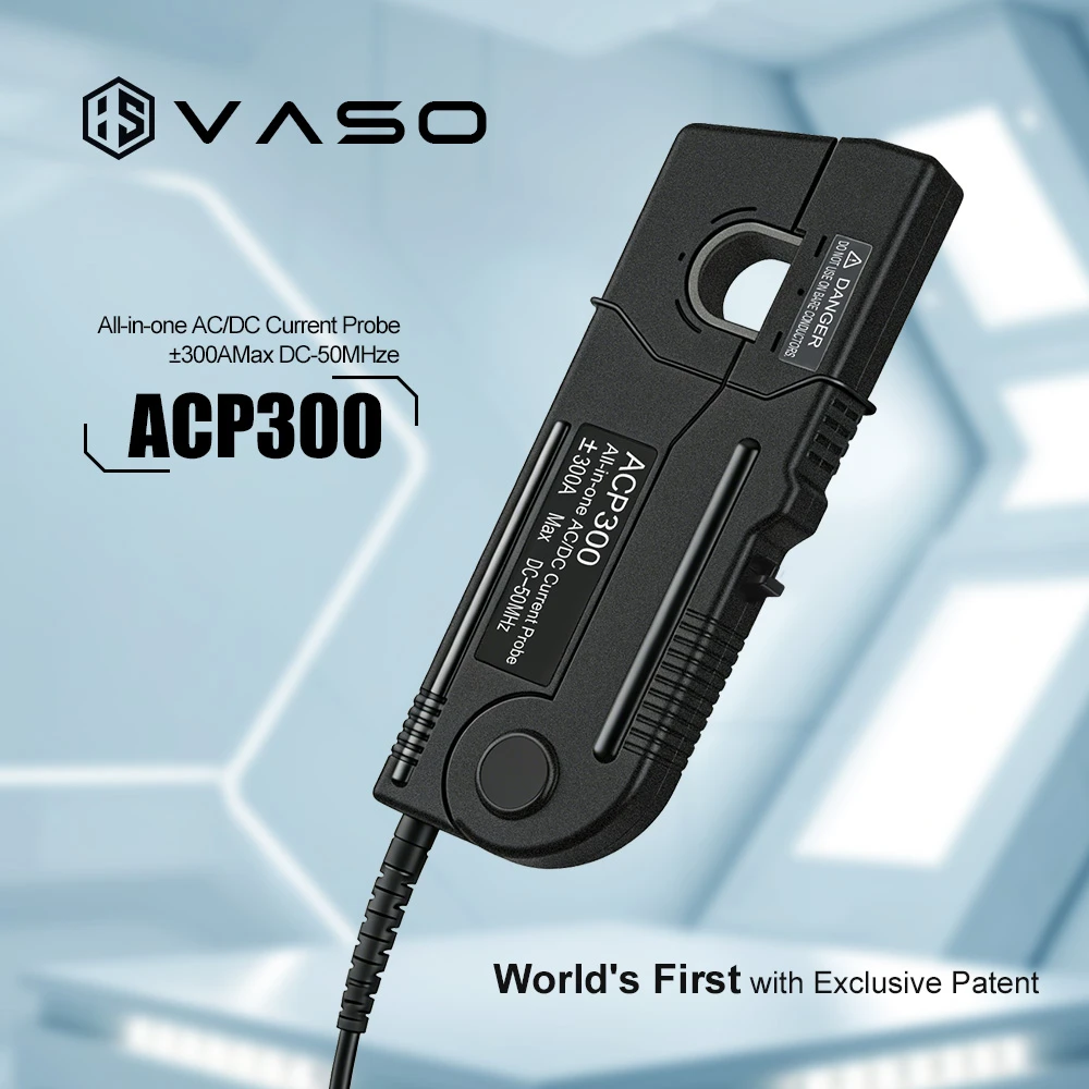
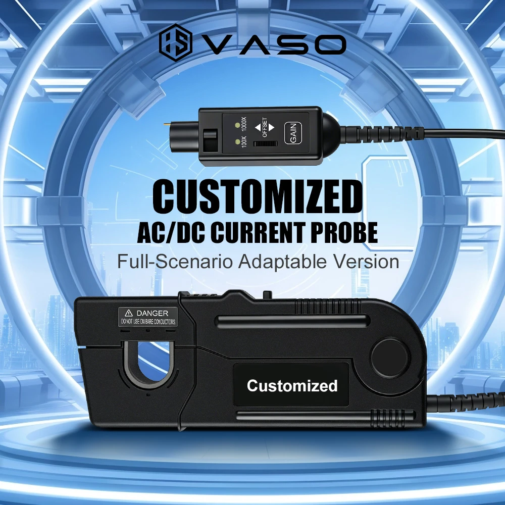
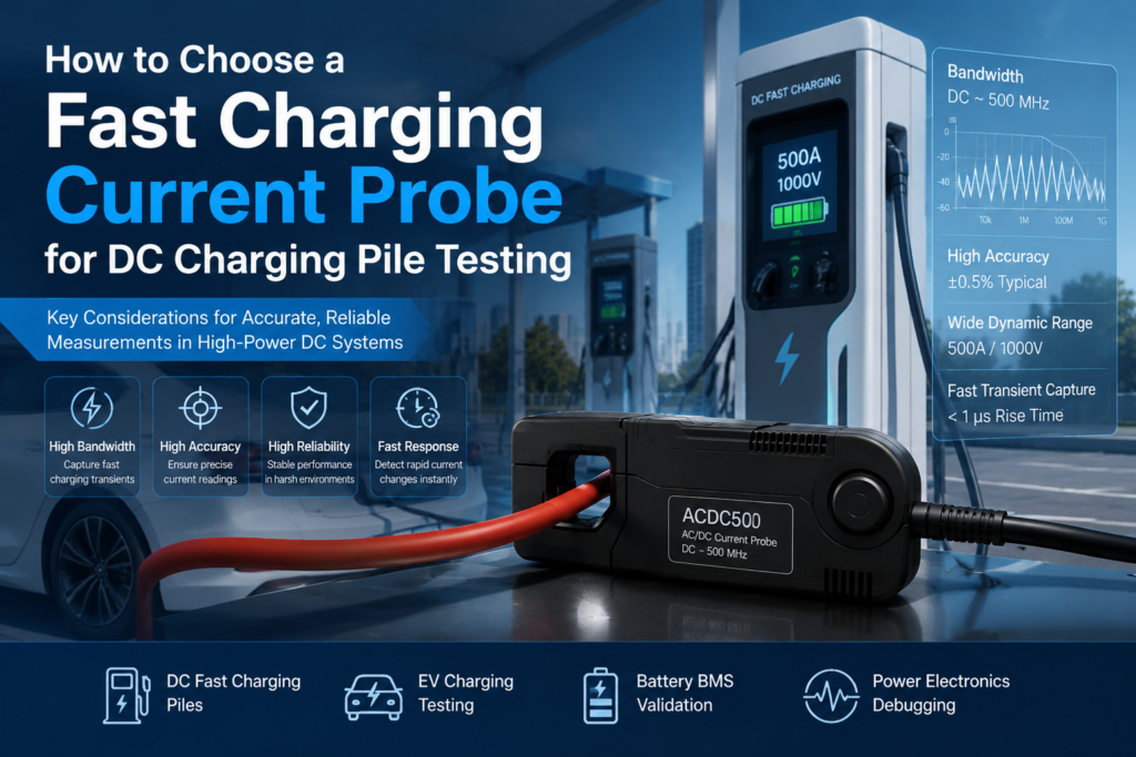
I’ve spent a good part of the last several years in EVSE test labs, standing next to 360 kW charging piles with an oscilloscope cart, trying to figure out why a “certified” current probe was giving us a ripple reading that didn’t match the power analyzer downstream. That mismatch, it turned out, came down to one thing: the probe was rated for the DC current we were pulling, but not for the frequency content actually riding on top of it. That’s the trap most people fall into when they shop for a current probe by amperage alone.
This article walks through what actually matters when selecting a probe for DC charging pile (EVSE/DCFC) testing — not the marketing bullet points, but the parameters that decide whether your data is trustworthy six months from now, under a different technician, on a different pile.
Why DC Fast Charging Makes Probe Selection Harder
A Level 2 AC charger is a relatively forgiving measurement target — low current, 50/60 Hz, no aggressive switching. A DC charging pile is a different animal entirely:
- Current levels now routinely span 125 A to 500 A per gun, with ultra-fast piles (CCS2/ChaoJi, 800 V architectures) pushing toward 600–1000 A in liquid-cooled cable systems.
- DC with superimposed switching ripple. The output isn’t clean DC — it’s the rectified, filtered output of a multi-module power stage (typically 15–40 kHz switching per module, sometimes interleaved). If your probe’s bandwidth rolls off before that switching frequency, you will systematically under-report ripple current, which directly affects your read on output capacitor stress and EMI compliance.
- Transient response during CC/CV and protocol handshakes. GB/T 27930 and DIN 70121/ISO 15118 communication triggers current step changes — the probe needs fast enough rise time to actually capture the pile’s real transient behavior, not just its steady-state number.
- High common-mode voltage. Chinese GB/T systems run up to 750–1000 V DC bus; European/US CCS architectures are moving to 800–920 V for 350 kW+ charging. The probe and its cabling need working voltage and isolation ratings that match, with real safety margin — not just enough to survive the nominal bus voltage.
None of this is exotic knowledge to anyone who has debugged a charging pile failure at 2 a.m., but it’s exactly the context that gets lost when a probe is chosen off a datasheet’s headline current rating.
The Core Selection Parameters
1. Current Range and Overload Margin
Don’t size the probe to your expected nominal current — size it to your worst-case transient. Charging piles regularly overshoot momentarily during connection, protocol renegotiation, or fault conditions. A probe rated exactly at 400 A on a system whose nominal current is 400 A will clip or saturate the first time the pile spikes to 420 A during a CV-to-CC transition. I generally look for at least 20–30% headroom above the pile’s rated maximum output current, and I check the datasheet specifically for the non-destructive overload rating, which is usually different (and lower) than the peak measurement range.
2. Bandwidth — This Is Where Most People Get Burned
This is the single most under-scrutinized spec, because “bandwidth” sounds like a nice-to-have rather than a correctness issue. It isn’t.
- If you only care about average charging current for efficiency or coulomb-counting tests, a few kHz of bandwidth is fine.
- If you’re characterizing output ripple, EMI pre-compliance, or module interleaving behavior, you need bandwidth well past the switching frequency of the power stage — practically speaking, DC to 1–2 MHz for most modern DCFC designs, and higher if you’re chasing switching-edge behavior rather than just the ripple envelope.
A probe that’s flat “DC to 100 kHz” will look perfectly fine on a scope trace and still be quietly attenuating the actual ripple content you’re trying to measure. If your test report is going to be used for an EMC pre-scan or a design validation sign-off, ask the probe vendor for the actual frequency response curve, not just a single bandwidth number — attenuation often starts well before the quoted -3 dB point.
3. DC Accuracy and Zero-Drift Behavior
Charging pile tests routinely run for hours — full charge cycles, thermal soak tests, cycle-life testing. A probe with poor DC offset stability will drift over a multi-hour test and silently corrupt your energy/efficiency calculations. This is where the underlying sensor technology matters:
| Technology | DC Response | Typical Use Case | Watch-Outs |
|---|---|---|---|
| Open-loop Hall effect | Yes | Cost-sensitive, mid-accuracy monitoring | Higher offset drift, more temperature sensitivity |
| Closed-loop (compensated) Hall effect | Yes | General-purpose EVSE bench testing | Good balance of accuracy, bandwidth, cost |
| Zero-flux / fluxgate | Yes | Precision efficiency & certification testing | Best DC accuracy and long-term stability; higher cost |
| Rogowski coil | No (AC only) | Ripple/AC component only | Cannot measure DC — must pair with a DC sensor if used |
| Shunt-based | Yes | High-precision, low-noise applications | No galvanic isolation — safety implications on high-voltage bus |
For anything involving certification-grade efficiency numbers (IEC 61851-23, or internal QA sign-off against a power analyzer), I default to closed-loop or zero-flux current probes. The extra cost is trivial compared to the cost of re-running a multi-hour thermal test because your DC baseline drifted 0.3% over four hours.
4. Isolation Voltage and Safety Rating
This is non-negotiable, and it’s the parameter I’ve seen most commonly under-specified by teams optimizing purely for bandwidth and accuracy. Your probe needs:
- A working voltage rating with real margin above the pile’s maximum DC bus voltage (for 800–1000 V systems, don’t run a probe rated at 600 V “because it usually doesn’t reach that high” — transients and pre-charge conditions do reach the rail voltage).
- A recognized CAT rating (per IEC 61010) appropriate for the measurement category of the point you’re probing — most DCFC internal bus measurements sit at CAT III or higher depending on where in the system you’re testing.
- Adequate creepage and clearance in the probe housing itself, not just the rated voltage number — cheap probes sometimes hit a voltage spec on paper without the physical isolation distances to back it up safely at altitude or in humid environments.
I don’t compromise on this parameter under any circumstance. A probe failure at high DC bus voltage isn’t a bad data point — it’s an arc-flash risk to whoever is standing next to the rig.
5. Physical Form Factor and Cable Compatibility
DC fast charging cables are thick — liquid-cooled cables in particular can exceed 25–30 mm in outer diameter. Confirm the probe’s jaw or aperture size actually clamps around your test cable with the cooling jacket or shielding intact, because stripping a liquid-cooled cable down to bare conductor to fit a smaller probe changes the thermal and impedance characteristics you’re trying to measure. I keep at least two probe form factors on hand for this reason — a compact probe for bench-level module testing and a large-aperture probe for full-cable, system-level tests.
6. Output Interface and Scope/DAQ Compatibility
Check connector type (BNC vs. proprietary), power supply requirements (battery vs. external), and whether the probe outputs a voltage proportional to current or needs a separate amplifier module. For long unattended test runs, battery-powered probes that auto-shutoff mid-test have burned more than one overnight cycle-life test I’ve been involved in — I now specifically favor probes with external/mains power or clear low-battery warning margins for anything running unattended overnight.
A Practical Selection Checklist
Before ordering, I run every probe candidate against this list, in this order:
- Does the current range cover worst-case transient current with margin, not just nominal current?
- Is the bandwidth sufficient for what I’m actually analyzing — average current, or ripple/switching behavior?
- Is the DC accuracy and drift spec adequate for the test duration (hours, not minutes)?
- Does the isolation/CAT rating exceed the actual DC bus voltage with real safety margin?
- Will it physically clamp the actual cable I’m testing, including cooling jackets?
- Can it run unattended for the full test duration without power interruption?
- Is it compatible with the oscilloscope, power analyzer, or DAQ I’m pairing it with?
If a probe fails any one of these, it doesn’t matter how good the rest of the spec sheet looks — I move on to the next candidate.
Final Thought
The recurring mistake I see — from junior test engineers and experienced ones alike — is treating current probe selection as a single-number decision (“we need a 600 A probe”). A DC charging pile is a high-voltage, high-current, high-frequency-content system all at once, and the probe sitting between your cable and your scope needs to be correct across all three dimensions simultaneously, not just the one that’s easiest to shop for. Get the bandwidth and isolation rating wrong, and the current number on your screen can still look plausible while being quietly wrong — which is a far worse outcome than an obviously broken measurement, because nobody catches it until the design fails downstream.