
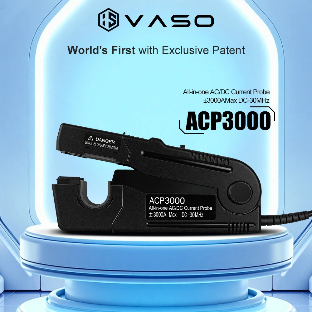
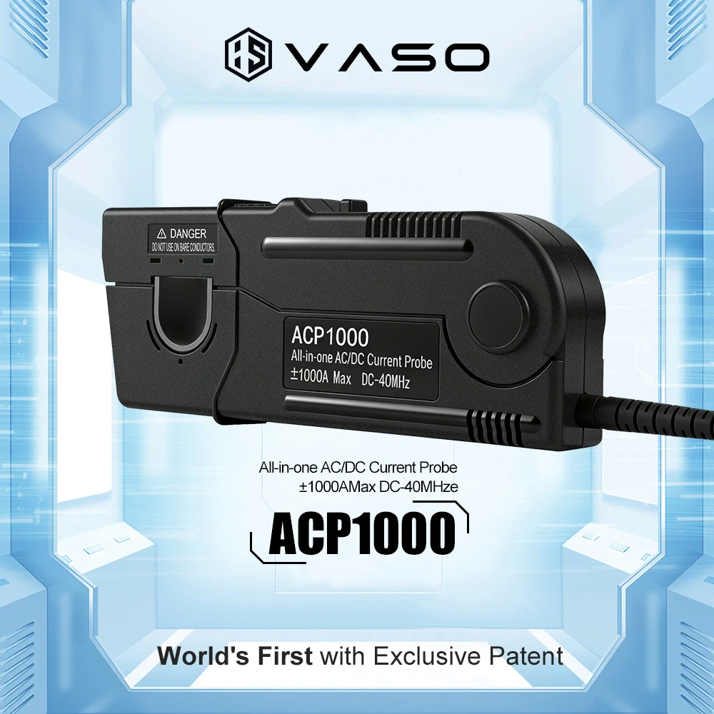
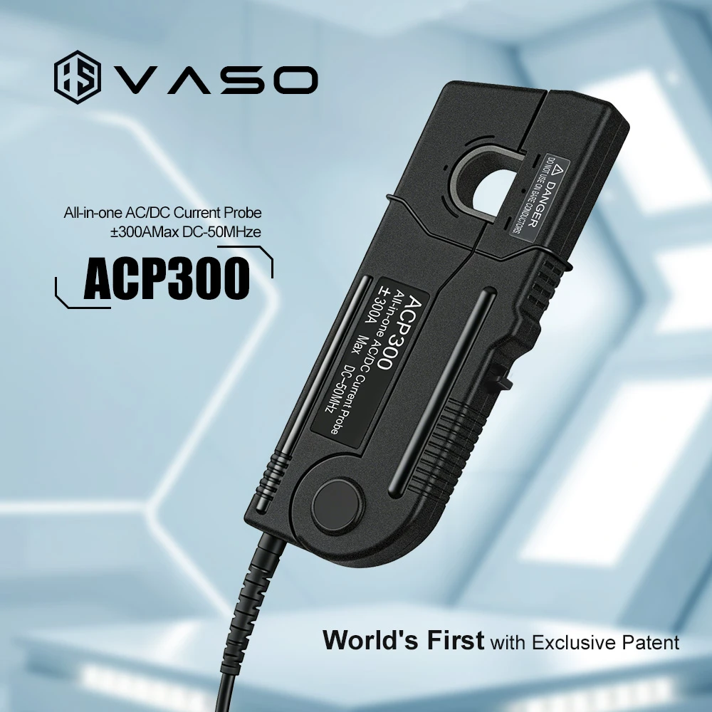
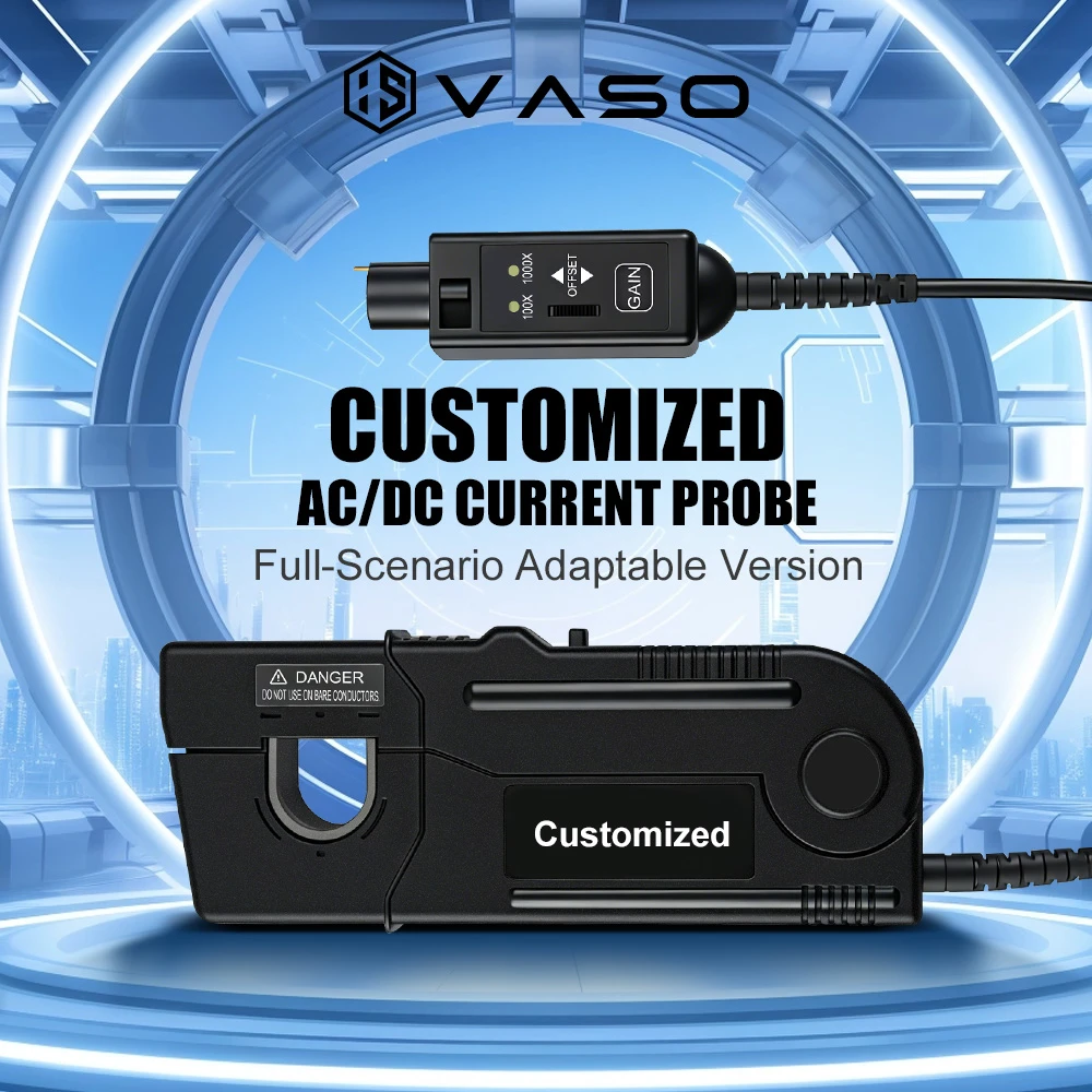
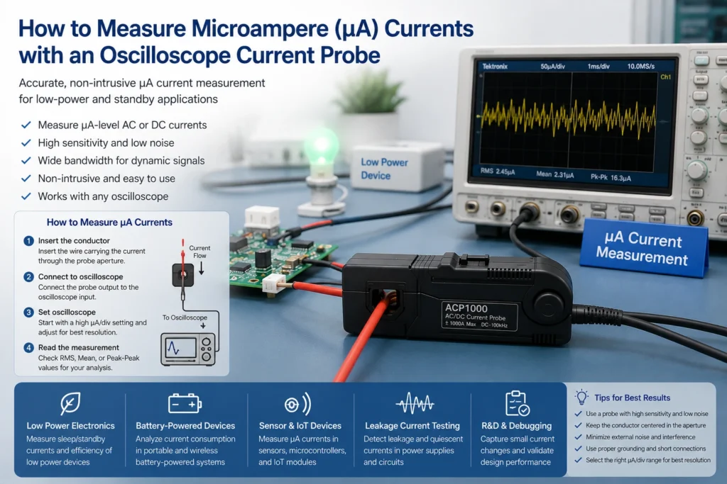
Trying to characterize the sleep-mode current of a battery-powered IoT sensor, a wearable, or any ultra-low-power MCU design often runs into the same frustrating wall: an oscilloscope current probe works beautifully down at the milliamp and amp level, but the moment the current drops into single-digit microamperes, the waveform basically disappears into the noise floor.
This is a well-known limitation, and there’s a genuinely useful bench trick — looping — that lets engineers push almost any clamp-style current probe further into the µA range without buying new hardware. The sections below cover why this problem happens, how the trick works, and where it falls short, since the technique tends to disappoint people who treat it as a magic fix rather than understanding the physics behind it.

Why an Oscilloscope Current Probe Struggles Below a Few Milliamps
Most clamp-on current probes — whether they’re simple passive transformer types or active AC/DC Hall-effect probes — work by sensing the magnetic field generated around a conductor. Current probes are available with current ratings ranging from microamperes all the way up to thousands of amperes, but maximum current handling and sensitivity are a direct trade-off. A probe built to comfortably handle tens of amps simply isn’t optimized to resolve a signal that’s six orders of magnitude smaller.
This isn’t a flaw in the probe — it’s physics. A probe with high current capability will typically lose resolution and accuracy when measuring a very low-amplitude signal near the bottom of its useful range, so sensitivity has to be considered in terms of both the probe and the oscilloscope together. When chasing microamps, the task is essentially asking a sensor designed for the “loud” end of the spectrum to pick out a whisper.
This exact problem shows up often in engineering forums dealing with Bluetooth Low Energy devices in deep sleep, where datasheets promise single-digit microamp consumption but real-world measurement proves tricky. One widely referenced discussion on this topic flagged the core issue directly: getting high-precision measurements with an oscilloscope is generally not easy, and it depends heavily on how good the scope itself is. The same thread pointed out something easy to overlook — the sense resistor chosen matters just as much as the probe. Using a larger sense resistor forces a lower sensitivity setting to avoid clipping, which ends up reducing accuracy, while too small a resistor makes common-mode currents more significant and also hurts accuracy. In other words, even before the probe gets involved, shunt design already shapes how much margin there is to work with.
The Looping Trick: Multiplying Sensitivity for Free
Here’s the part that actually changes things. If the wire carrying a tiny current is wrapped through the probe’s core multiple times instead of passed through once, the probe’s output scales up proportionally. This isn’t a hack unique to one brand — it’s documented behavior across the industry. Tektronix application notes describe this directly: engineers can increase current sensitivity by wrapping N turns of the conductor around the current probe. DigiKey’s technical writeup on current probe selection describes the same approach, noting that when measuring small currents, the sensitivity of a current probe can be increased by wrapping multiple turns through the primary, and explains the underlying reason: as in any transformer, the probe’s sensitivity increases with the number of turns passing through the probe core.
So the math is straightforward:
Actual current = Displayed reading ÷ Number of turns
Wrap the conductor through the core 10 times, and a 5 µA real current shows up on screen looking like 50 µA. Divide by 10, and the result is back to ground truth — except now that signal sits comfortably above the noise floor instead of getting lost in it.
Applying the Technique on the Bench
The execution is genuinely low-tech. Start by identifying the conductor feeding the device under test, stripping a bit of insulated wire for extra length if needed, then loop it back and forth through the probe jaw or aperture. Loops should stay loose and evenly spaced rather than tightly bunched — a sloppy, crossed-over winding can introduce its own measurement artifacts. Each pass through the core needs to be counted carefully; miscounting by even one turn throws off the entire calculation, and it’s an easy mistake to make once the winding goes past five or six wraps.
Once the loops are in place, the reading is taken as normal, then divided by the turn count. Labeling the turn count directly on the probe body or test setup is a smart habit during longer sessions involving multiple measurements — an unrecorded turn count is a common source of reporting a number several times too high.
This same physical principle gets used in reverse for a different purpose, which helps illustrate why looping works at all. Some probe documentation describes enclosing multiple separate conductors through the probe core to make a differential measurement — a reminder that the core’s response is really just counting net ampere-turns, not “looking at one wire.”
Where the Trick Hits Its Limits
Looping isn’t free. Adding turns through a ferromagnetic core adds inductance to the circuit under test, and for fast transients or anything frequency-sensitive, that extra inductance can distort exactly the signal being studied. For DC consumption measurements or slow sleep/wake current profiling, it’s rarely an issue. For anything switching at MHz speeds, it’s worth checking before trusting the waveform.
The bigger limitation, though, is one that trips up a lot of people: looping multiplies the signal, but it multiplies the probe’s noise and nonlinearity right along with it. If the probe’s baseline noise floor is high relative to true µA-level signals, ten or twenty turns won’t rescue the measurement — it’s just amplifying noise alongside the signal of interest. Engineers on TI’s support forums have run into exactly this wall when chasing single-digit microamp currents on ultra-low-power MCUs, eventually concluding that non-contact current probes capable of resolving such low currents tend to be very expensive, and that a shunt resistor combined with a precision low-offset amplifier was a more practical path for getting down near 1 µA.
That’s the honest trade-off: looping is a great force-multiplier on a probe that already has decent low-noise performance, but it can’t manufacture sensitivity a probe simply doesn’t have. This is exactly why test engineers who routinely work in the low-µA range — power electronics designers, IoT and wearable developers, certification lab technicians — tend to gravitate toward current probes built with genuinely low noise floors and clean low-current linearity in the first place. The probe sets the ceiling on how far looping can take a measurement; it doesn’t replace the need for a quality instrument.
A Few Practical Notes Before Trying It
Most modern active probes, like Tektronix’s AC/DC current probes or similar Hall-effect designs, include degauss and auto-zero functions — degaussing should be performed before any critical measurement to ensure the best accuracy, and auto-zero sets the probe’s output offset to zero when no current is flowing. Running both before looping is a good habit. Residual core magnetization or a small DC offset gets multiplied by the turn count just like everything else, so an error that was negligible at 1x can become noticeable at 10x or 20x.
It’s also worth double-checking the scope’s vertical scaling after looping. Many oscilloscope current probe systems auto-scale based on the probe’s known sensitivity — for example, a probe with a sensitivity of 1 volt per amp communicates that scaling to the oscilloscope so the channel automatically reads out in amperes. That auto-scaling has no way of knowing extra turns have been added, so the multiplier needs to be applied manually when interpreting the displayed value.
The Bottom Line
Looping is one of those bench techniques that feels almost too simple to be legitimate, but it’s standard practice precisely because the underlying physics is sound — it’s just transformer action, applied deliberately. For anyone trying to characterize µA-level currents without buying a dedicated ultra-sensitive probe, it’s worth trying before anything else. The realistic expectation is that it amplifies whatever the oscilloscope current probe is already capable of, noise included. For serious, repeatable microampere work, pairing the looping technique with a probe that already has a low inherent noise floor is what actually delivers reliable numbers — not the looping alone.